Battery Discharge Indicator 02
|
DESCRIPTION
Model BDI02 is an inexpensive,easy to install Battery Discharge Indicator (BDI). It is completely solid state and provides a reliable, accurate, and easy to read display of battery state of charge.
APPLICATION
This battery discharge indicator is ideal for golf cars, hunting buggies, commercial leaning equipment, mobility aids, electric bicycles, and similar equipment.
FEATURES
1: Higher integrated circuits for long-life reliability.
2: A 10-bar high light LED displays the state of charge.
3: At 70% depth of discharge, a flashing LED
signals an ENERGY RESERVE alert.
4:At 80%, alternately flashing LEDs provides an EMPTY status warning.
5: It is compact and easy to install.
6: Recognizes improperly charged battery.
7: Key switch activated LED display (state of charge is monitored as long as the BDI is connected to battery).
8: Lens Material: Plastic
9: Case Material: ABS KJW, Black
RESET METHODS
1: Open Circuit Reset (OCR).
Upon reconnection of a battery, the BDI will reset to the full status if it measures 2.09 volts/cell or higher.
2: Battery Charging Reset (BCR)
The BDI will reset to the full state when the BDI measures the voltage of per cell up to 2.35 volts or higher.
OPTIONS
GREEN WIRE(O) is the collector of a triode without high drive ability,will output a low voltage at 70% discharge of battery. It can be used to signal another component or to allow for the disabling of a specified vehicle function, insuring against abusive deep discharge conditions.
(Note: Output Saturation Voltage: 300 mV (Type) at 10 mA; Maximum VCE is 40V)
SPECIFICATIONS
1: System voltages: 12V, 24V, 36V, 48V, 72V
2: Operating voltage: +/-25% of normal voltage
3: Operating temperature:-20Celsius degree to +75Celsius degree
4: Storage temperature: -40Celsius degree to +90Celsius degree
5: Shock & Vibration: Meets SAE J 1378
SCHEME

Fig.1.1 The scheme of BDI02
(Note.2: This gage is not intended to measure the state of charge of batteries subject to extended periods of inactivity since it does not account for self-discharge effects. Consult factory for details.)
TERMINALS AND WIRING
P:Battery + N:Battery-
RED WIRE BLACK WIRE
O:Output Signal K:Key Switch
GREEN WIRE YELLOW WIRE
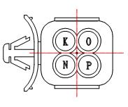
Fig.2.1 Wring diagram
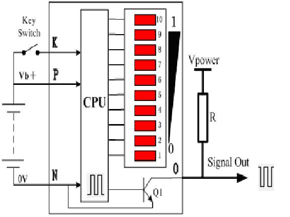
Fig.2.2 Wring diagram
DIMENSION (mm)

The shell of BDI02

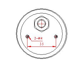
(see Apendix)